KV-X 系列 × MP-F 系列
EtherNet/IP™ 连接指南
KV-X 系列 × MP-F 系列 EtherNet/IP™ 连接指南
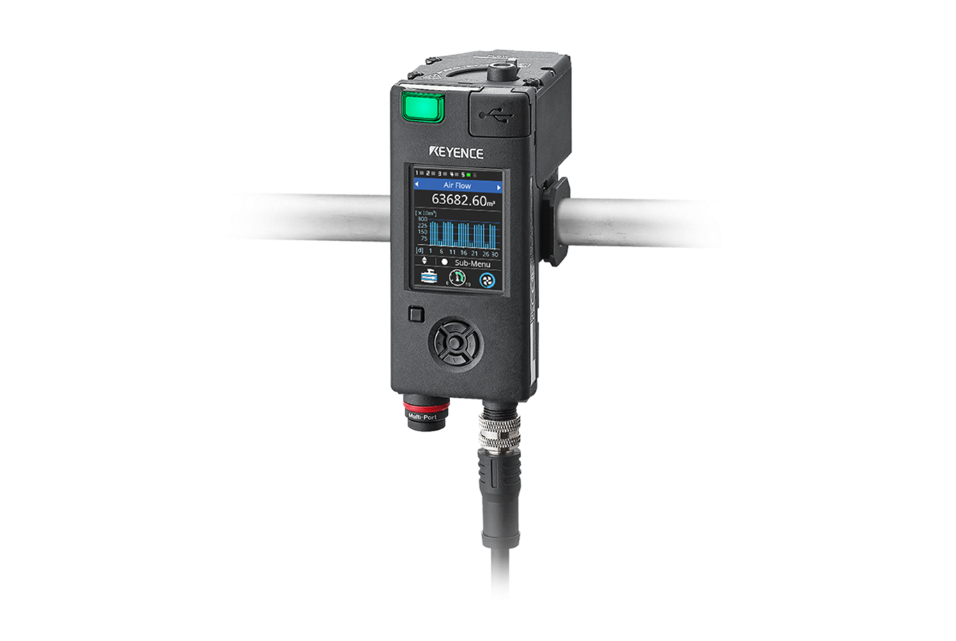
MP-F 系列

内容
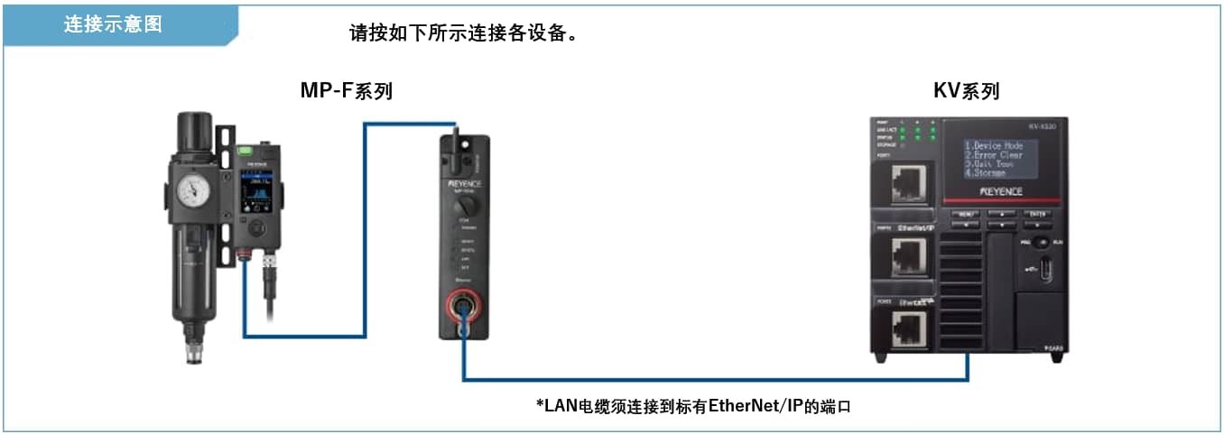
步骤 1 : 连接所需设备
MP-F 系列
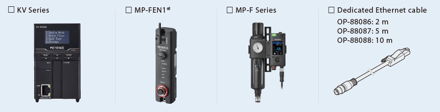
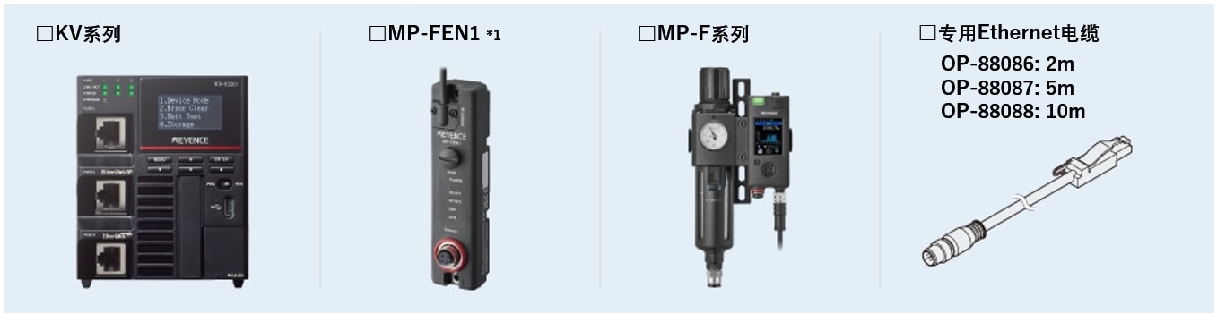
※1 一台 MP-F 系列设备需要一个Ethernet模组 (MP-FEN1)。

步骤 2 : MP-F 系列的 EtherNet/IP 设定
MP-F系列的EtherNet/IP设定需要通过Ethernet模组MP-FEN1来设定。
有以下 MP-FEN1 设置方法可供选择。
(1) 从 KV STUDIO 进行设置(*此设置只有在 MP-FEN1 处于初始状态时才能进行)。
(2) 从 MP-F 系列进行设置
(3) 从 MP-F Monitor(MP-F 系列软件)进行设置
在初始状态以外的状态下,以及在 MP-F 系列的外部输入设置中,请使用设置方法 (2) 或 (3)。(关于方法 (3),请参阅 “要点”)。
本手册介绍 KV STUDIO 的设置步骤。
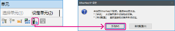
1. 打开 KV STUDIO 的单元编辑器,然后单击 EtherNet/IP 设定图标。显示EtherNet/IP设定对话框。单击 [手动 (M)]。
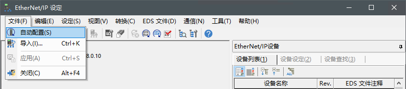
* 需要导入传感器配置文件时执行步骤 2。如果已经导入了传感器配置文件,请通过 LAN 电缆连接 KV Series 和传感器设备,然后单击 [自动配置 (A)],再进入步骤 3。
2. 显示 [EtherNet/IP 设定] 窗口。选择 [EDS 文件 (D)] ⇒ [Reg (I)],导入用于 MP-F 系列的 KEYENCE 传感器配置文件(ez1 文件)。
3. 通过以太网电缆连接 KV 系列和传感器设备后,在 [EtherNet/IP 设定] 窗口中选择 [文件 (F)] ⇒ [自动配置 (S)]。
要点
本节介绍 MP-F 显示器的设置步骤。
- MP-FEN1 和 KV 系列通过 LAN 电缆连接。
- 为 MP-FEN1 和 KV 系列供电。
- 使用以太网交换机时,用 LAN 电缆将以太网交换机连接到 MP-FEN1 和 KV 系列,并向以太网交换机供电。
4. 当单元编辑器中的配置与实际设备的配置不同时,将显示确认项目传输的对话框。用 USB 电缆连接 PC 和 KV 系列后,单击 [是 (Y)]。
项目传输完成后,将显示 [设备查找设定] 对话框。然后单击 [查找 (F)]。
从搜索结果中选择未指定的 MP-FEN1,然后单击 “未指定”。
显示 [IP地址设定] 对话框。然后,将 MP-FEN1 的 IP地址设定为 “192.168.0.1”,然后单击 [OK]。

要点
单击  [IP地址设定] 对话框可搜索未使用过的 IP 地址。
要点
本节介绍 MP-F 显示器的设置步骤。
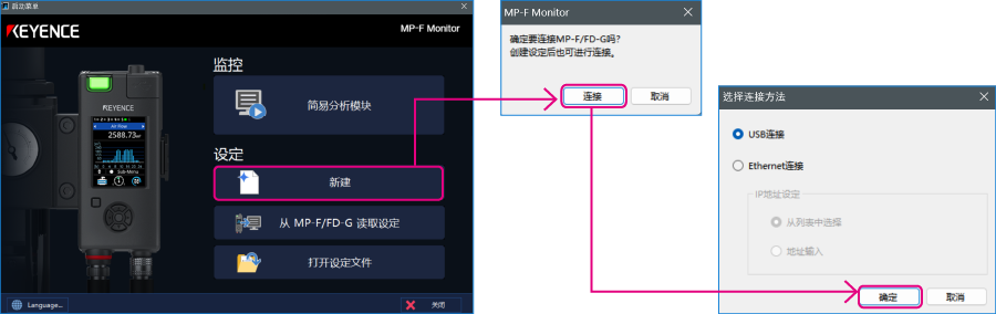
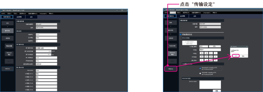
1. 使用 USB 电缆(OP-51580:2 m/OP-86941:5 m)连接 PC 和 MP-F,并使用专用电缆连接 MP-F Series 和 MP-FEN1。启动 MP-F Monitor,然后单击 [新建] - [连接]。显示 [选择连接方法] 对话框。选择 “USB 连接”,然后单击 [确定]。
2. 单击 [Ethernet模组],配置 MP-F 系列的以太网设置。在 “传输通信设置 ”中打勾,并按下图所示进行设置。

<Ethernet 设定>
| TCP 端口号 | 8637 |
|---|---|
| IP 设置 | Fixed IP |
| IP 地址 | 192.168.0.1 |
| 子网掩码 | 255.255.255.0 |
| 默认网关 | 0.0.0.0 |
3. 选择 [基本设定],将 “阀门操作设定 ”设为 “外部输入控制”。设置完成后,单击 [ 传输设定 ],然后单击 [ OK ] 将设置内容传输到 MP-F 系列。
* 从 PLC 执行阀门控制时需要此设置。
步骤 3 : KV-X 系列的设置
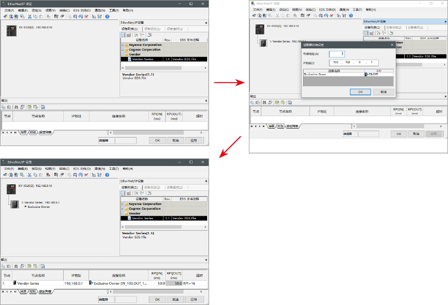
本节将介绍如何连接名为「Vendor Series」的虚拟设备,实际使用时请将「Vendor Series」替换为要连接的设备。
要点
KV-X 系列上,可以给EtherNet/IP的连接分配变量。
给EtherNet/IP的连接分配变量时,在[CPU系统设定]对话框的“系统设定”的“其他设定”中勾选“EtherNet/IP设置更新时显示变量设置对话框(E)”。
从“KV STUDIO”的菜单中选择【视图(V)】⇒【CPU系统设定(P)】,即显示[CPU系统设定]对话框。
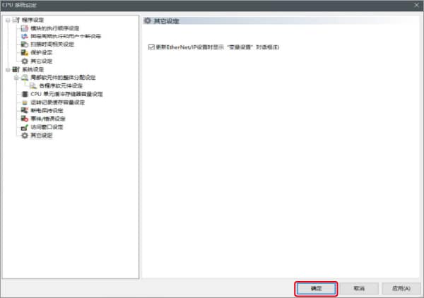
勾选“EtherNet/IP设置更新时显示变量设置对话框(E)”后,即更新EtherNet/IP设置,当确定了单元编辑器的更改内容时,即显示给连接分配变量的对话框。
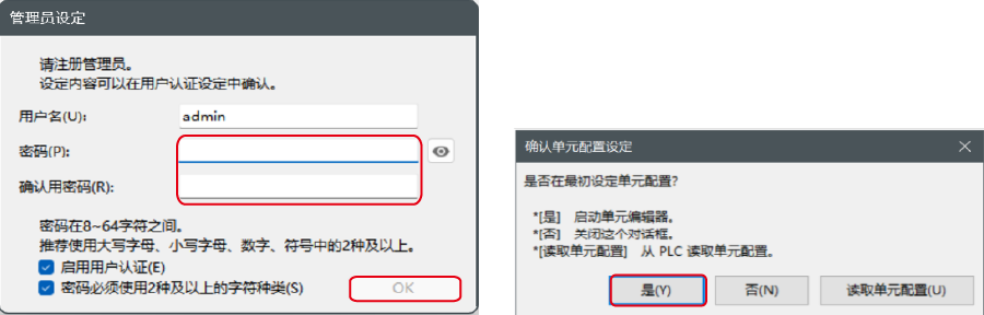
1.启动KV STUDIO,新建项目。支持型号选择“KV-X520”,单击〔OK〕。

显示[管理员设定]对话框,输入密码后点击[OK],显示[确认单元配置设定]对话框,单击〔是(Y)〕。
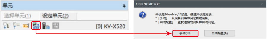
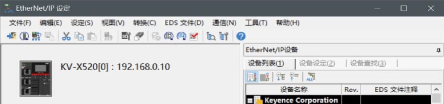
2.在单元编辑器上单击EtherNet/IP设定的图标。显示选择设置方法的对话框,单击〔手动(M)〕。
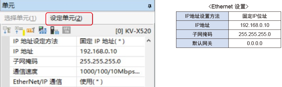
3.显示单元编辑器,在“设定单元(2)”选项卡中设置KV-X520的IP地址。在此,如下所示设置。
* Step4是导入传感器设置文件时的步骤。已经导入传感器设置文件时,请进入Step5。
4.显示[EtherNet/IP设置]窗口,选择【EDS文件(D)】→【注册(I)】,导入基恩士公司制传感器设置文件(ez1文件)。
* 可从Keyence官方网站下载传感器设置文件。
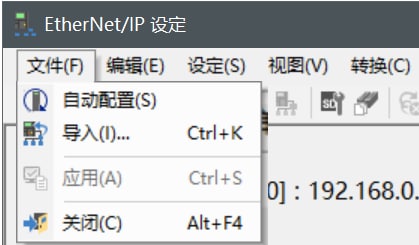
5. 在用Ethernet电缆连接了KV-X 系列IV4 系列的状态下,选择[EtherNet/IP设定]窗口的【文件(F)】→【自动配置(S)】。
6.实机和单元编辑器的配置不同时,会显示确认项目传输的对话框,在用USB电缆连接了PC和KV-X 系列的状态下单击〔是(Y)〕。
7.项目传输完成后,显示[设备查找设定]对话框,单击〔查找(F)〕。自动配置完成后,IV4 系列会自动注册,单击〔OK〕关闭[EtherNet/IP设置]窗口。

8.单击单元编辑器的〔OK〕退出。
要点
已勾选“EtherNet/IP设置更新时显示变量设置对话框(E)”时,显示[EtherNet/IP设备 变量设置]对话框。
输入分配给连接的变量的变量名,单击〔OK〕。

- 手动设置的方法
设置设备配置的方法在"EtherNet/IP设定"的[设备列表(1)]选项卡中,拖放“Vender Series”并创建设备配置。
设置数据的传输和监控器
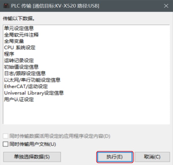
1.从菜单中选择【监控器/模拟器(N)】>【PLC传输→监控器模式(C)】。
在[PLC传输]对话框中单击〔执行(E)〕。
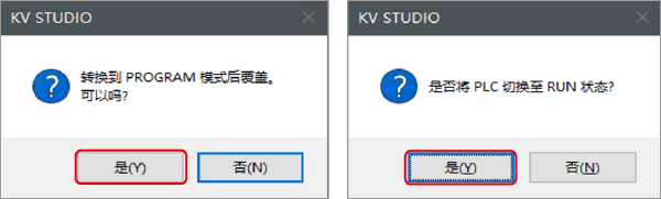
2. 如果在传输数据之前和之后的显示以下对话框,请两次分别点击[是(Y)]。
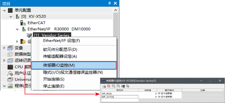
3. 在工作空间的“Vender Series”上右键单击,选择【传感器IO监控(M)】。
可简单监控传感器中的信息。
要点
也可以启动实时时序图监控器,在图表上确认。
在“传感器IO监控”上右键单击,选择【实时时序图监控器(H)】。
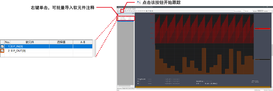
不需要调整范围,因为即时时序图监控器会自动执行缩放。
如何通过程序来修改相关参数
从而更改设定值
传感器的设定值可以通过如下两种方法更改:
A : 从PC更改
B : 从梯形图程序更改
* 以下将以传感器MU-N(FD-0*C)为例进行说明。
A : 从PC更改
要从PC更改设定值,请使用KV STUDIO中的传输适配器功能
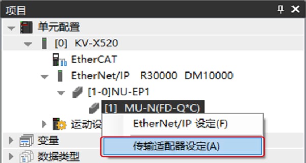
1. 在工作空间中展开单元配置。右键点击MU-N(FD-0*C)并选择[传输适配器设定(A)]
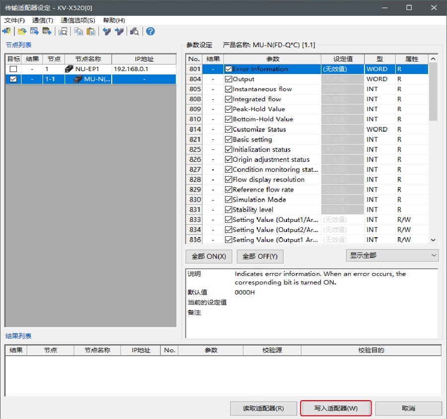
2. 在「MU-N(FD-0*C)」的参数上打勾,然后输入设定值。
点击 [写入适配器 (W)] 将设定值写入传感器。
*要读取传感器的设定值,请选择 [读取适配器 (R)]。
B : 从梯形图程序更改
通过梯形图程序,执行显示报文通讯来更改设定值。
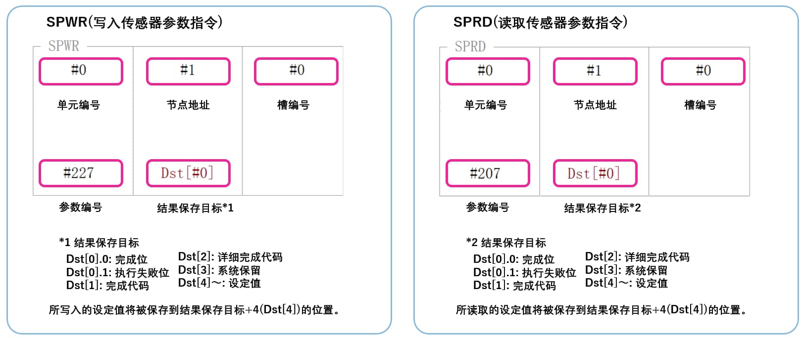
如需进行显式报文,请使用传感器设置指令(SPWR 指令(写入传感器参数指令)、SPRD 指令(读取传感器参数指令))
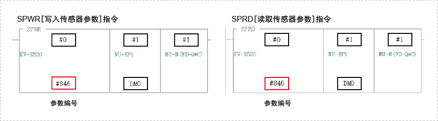
1. 在编辑器模式下,创建一个梯形图程序,如下所示
* 关于参数编号的具体信息,请参照对应的参数表
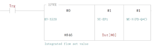
2. 传输梯形图程序到PLC
3. 当Trg变为ON状态时,相对应的设置值会被改写
* 将设定值储存在Dst[#4] 中([结果储存位置] + 4)。
要点
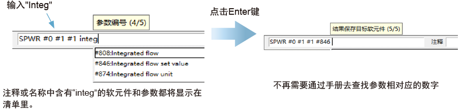
RT(即时)编辑功能
当您使用梯形图程序时,您可以直接将软元件注释或者参数名输入到自动搜索并显示输入候选项。
步骤 4 : 控制截止阀门的梯形图示例
可在 PLC 上对截止阀门进行开/关控制。本节展示了示例梯形图。
* MP-F 系列的阀门控制设置需要设置为 “外部输入控制”。(见要点)
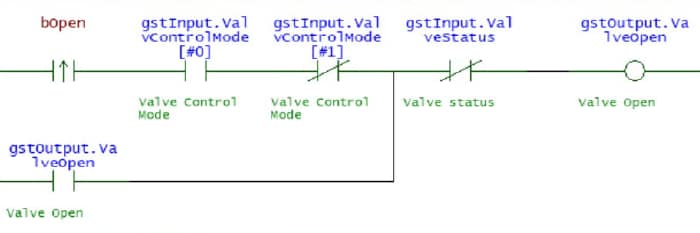
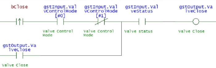
1. 将 KV STUDIO 设为编辑器模式。在梯形图程序中,创建梯形图来控制截止阀门。将控制设置设为 “外部输入控制 ”时,该程序将请求直到阀门状态发生变化。
阀门打开请求
阀门关闭请求
助记符列表
LDP bOpen
AND gstInput.ValvControlMode[#0] ANB gstInput.ValvControlMode[#1] OR gstOutput.ValveOpen
ANB gstInput.ValveStatus OUT gstOutput.ValveOpen
LDP bClose
AND gstInput.ValvControlMode[#0] ANB gstInput.ValvControlMode[#1] OR gstOutput.ValveClose
AND gstInput.ValveStatus OUT gstOutput.ValveClose
2. 将创建的程序传输到 PLC。
选择 [监控器/模拟器 (N)] ⇒ [PLC传输 ⇒ 监控器模式 (C)],然后单击 [执行]。
3. 将 PLC 设置为 “RUN(运转状态)”。
4. 在〈KV STUDIO〉监控器中使用上述程序打开时,将 “bOpen ”设为 ON,关闭时将 “bClose ”设为 ON,以控制截止阀。
要点
⇒ 无需参照手册来创建梯形图程序!
只要在输入操作数时输入部分变量/软元件注释,就能输入继电器编号。(RT 编辑功能)
省去了查找继电器号码的时间,减少了创建程序的工时。

补充 : 存储器映射
MP-F 系列 [EtherNet/IP] 设置
以下是循环通信和报文通信中可以交换的参数列表。
▶ 可在循环通信中获得的参数列表
由于在循环通信中可以获得的参数会在 KV 系列和 MP-F 系列之间的固定内部自动更新,因此不需要用于读写数据的程序。以下是分配给变量时的存储器映射图。
MP-F 系列 → KV 系列
| Member Name | Data Type | Detail |
|---|---|---|
| Ch1_Output | BOOL | Ch.1 Output |
| Ch2_Output | BOOL | Ch.2 Output |
| Ch3_Output | BOOL | Ch.3 Output |
| Ch4_Output | BOOL | Ch.4 Output |
| Ch5_Output | BOOL | Ch.5 Output |
| Ch2_Input | BOOL | Ch.2 Input |
| Ch3_Input | BOOL | Ch.3 Input |
| Ch6_Input | BOOL | Ch.6 Input |
| ZeroFlow | BOOL | Zero flow |
| ValveStatus | BOOL | Valve status |
| ValveControlReq | BOOL | Valve Control Request |
| ValvControlMode | ARRAY[0..1] OF BOOL | Valve Control Mode |
| CycleStatus | BOOL | Cycle status |
| FlowMeasurement | BOOL | Flow measurement |
| PressureMeasurement | BOOL | Pressure measurement |
| TempMeasurement | BOOL |
Temperature measurement |
| HumidityMeasurement | BOOL | Humidity measurement |
| DewPointMeasurement | BOOL |
Dew point measurement |
| DetectableStatus | BOOL | Detectable Status |
| HistoryDataReady | BOOL | History data ready |
| InstantFlow | UINT | Instant.Flow |
| InstantFlow_Peak | UINT | Instant.Flow_Peak |
| InstantFlow_Bottom | UINT | Instant.Flow_Bottom |
| LeakageFlowRate | UINT | Leakage flow rate |
| SavedLeakFlowRate | UINT | Saved leak flow rate |
| AccumulatedFlow | UDINT | Accumulated Flow |
| Pressure | INT | Pressure |
| Pressure_Peak | INT | Pressure_Peak |
| Pressure_Bottom | INT | Pressure_Bottom |
| Temperature | INT | Temperature |
| DewPoint | INT | Dew point |
| Humidity | UINT | Humidity |
| ActivePower | DINT | Reactive Power |
| ApparentPower | DINT | Apparent Power |
| AccumActEnergy | UDINT | Accum. Act.Energy |
| AccumAppEnergy | UDINT | Accum. App.Energy |
| AccumFlow_Cycle | UDINT | Accum. Flow/Cycle |
| ElecEnergy_Cycle | UDINT | Elec. Energy/Cycle |
| CycleTime | UDINT | Cycle Time |
| FlowCycle_Today | UDINT | Flow/Cycle (Today) |
| EnergyCycle_Today | UDINT | Energy/Cycle(Today) |
| CycleTime_Today | UDINT | Cycle time (Today) |
| CycleCount_Today | UDINT | Cycle count (Today) |
| ElapsedTime_Today | UDINT | Elapsed Time(Today) |
| OperatTime_Today | UDINT | Operat. Time(Today) |
| Year | UINT | Year |
| Month | UINT | Month |
| Day | UINT | Day |
| Hour | UINT | Hour |
| Minute | UINT | Minute |
| sec | UINT | sec |
| ErrorInformation | UINT | Error Information |
| Reso_InstantFlow | UINT | Reso_Instant.Flow |
| Reso_Pressure | UINT | Reso_Pressure |
| Reso_Temperature | UINT | Reso_Temperature |
| Reso_Humidity | UINT | Reso_Humidity |
| Reso_DewPoint | UINT | Reso_Dew point |
| Reso_AccumFlow | UINT | Reso_Accum. Flow |
| Reso_ElecPower | UINT | Reso_Elec. Power |
| Reso_ElecEnergy | UINT | Reso_Elec. Energy |
KV 系列 → MP-F 系列
| Member Name | Data Type | Detail |
|---|---|---|
| AccumFlowReset | BOOL | Accum. flow reset |
| ZeroFlow | BOOL | Zero flow |
| ValveOpen | BOOL | Valve Open |
| ValveClose | BOOL | Valve Close |
| CycleStart | BOOL | Cycle Start |
| CycleStop | BOOL | Cycle Stop |
| AccumEnergyReset | BOOL | Accum. energy reset |
| HoldReset | BOOL | Hold reset |
| Reserved |
ARRAY[0..15] OF BOOL |
▶ 可在报文通信中获取的参数列表
报文通信是一种通信方法,用于在任意时间交换数据,如更改设置值。报文通信需要使用梯形图程序进行通信。不过,KV 系列可使用专用指令字(SPWR/SPRD 指令)与 KEYENCE 基恩士传感器进行通信。
| Attribute ID | Parameter No. | Item |
|---|---|---|
| 500 | 500 | Model |
| 501 | 501 | Ethernet module Connection |
| 502 | 502 | Energy Monitor 0 Connection |
| ~ | ~ | ~ |
| 511 | 511 | Energy Monitor 9 Connection |
| 512 | 512 | IO-Link serial number |
| 514 | 514 | IO-Link serial number |
| 516 | 516 | IO-Link serial number |
| 518 | 518 | IO-Link serial number |
| 520 | 520 | I/O Status |
| 521 | 521 | Device Status |
| 522 | 522 | Error Information 1 |
| 524 | 524 | Error Information 2 |
| 526 | 526 | Error Information 3 |
| 600 | 600 | Command Execution |
| 601 | 601 | Command Statuses |
| 1000 | 1000 | PNP/NPN |
| 1001 | 1001 | Ch.1 I/O Type |
| 1002 | 1002 | Ch.1 Target |
| 1003 | 1003 | Ch.1 Logic |
| 1004 | 1004 | Ch.1 Detection Mode |
| 1005 | - | Reserved for System |
| 1006 | 1006 | Ch.1 Low Threshold |
| 1008 | 1008 | Ch.1 High Threshold |
| 1030 | 1030 | Ch.1 Analog Target |
| 1031 | - | Reserved for System |
| 1032 | 1032 | Ch.1 Analog Lower Limit |
| 1034 | 1034 | Ch.1 Analog Upper Limit |
| 1100 | - | Reserved for System |
| 1101-1200 | - | (Ch.2) |
| 1201-1300 | - | (Ch.3) |
| 1301-1400 | - | (Ch.4) |
| 1401-1500 | - | (Ch.5) |
| 1501-1600 | - | (Ch.6) |
| 2000 | 2000 | Instant.Flow |
| 2001 | 2001 | Instant.Flow_Peak |
| 2002 | 2002 | Instant.Flow_Bottom |
| 2003 | - | Reserved for System |
| 2004 | 2004 | Accumulated Flow |
| 2006 | 2006 | Leakage flow rate |
| 2007 | 2007 | Saved leak flow rate |
| 2008 | 2008 | Reso_Instant.Flow |
| 2009 | 2009 | Reso_Accumulated Flow |
| 2020 | 2020 | Pressure_ Current value |
| 2021 | 2021 | Pressure_Peak |
| 2022 | 2022 | Pressure_Bottom |
| 2023 | 2023 | Reso_Pressure |
| 2030 | 2030 | Temperature _ Current value |
| 2031 | 2031 | Dew point _ Current value |
| 2032 | 2032 | Humidity _ Current value |
| 2033 | 2033 | Dew point_Enabled |
| 2034 | 2034 | Humidity_Enabled |
| 2035 | 2035 | Reso_Temperature |
| 2036 | 2036 | Reso_Dew point |
| 2037 | 2037 | Reso_Humidity |
| 2040 | 2040 | Valve status Monitor |
| 2041 | 2041 | Valve Control Request Status |
| 2042 | 2042 | Valve Operation Method |
| 2043 | 2043 | Valve Thres. Calibration Status |
| 2044 | 2044 | Valve Close Threshold |
| 2045 | - | Reserved for System |
| 2050 | 2050 | Total Active Power |
| 2052 | 2052 | Reserved for System |
| 2054 | 2054 | Total Apparent Power |
| 2056 | 2056 | Total Accum. Act.Energy |
| 2058 | 2058 | Reserved for System |
| 2060 | 2060 | Total Accum. App.Energy |
| 2062 | 2062 | Common(Energy)_System A Address |
| ~ | ~ | ~ |
| 2071 | 2071 | Common(Energy)_System J Address |
| 2072 | 2072 | Reso_Phase Voltage |
| 2073 | 2073 | Reso_Line Voltage |
| 2074 | 2074 | Reso_Current |
| 2075 | 2075 | Reso_Active Power |
| 2076 | 2076 | Reso_Reactive Power |
| 2077 | 2077 | Reso_Apparent Power |
| 2078 | 2078 | Reso_Accum. Act.Energy |
| 2079 | 2079 | Reso_Accum. Rct.Energy |
| 2080 | 2080 | Reso_Accum. App.Energy |
| 2081 | 2081 | Reso_Frequency |
| 2082 | 2082 | Reso_Power Factor |
| 2100 | - | A_Phase Voltage_1 |
| 2101 | - | A_Phase Voltage_2 |
| 2102 | - | A_Phase Voltage_3 |
| 2103 | - | A_Phase Voltage_(Average) |
| 2104 | - | A_Line Voltage_1 |
| 2105 | - | A_Line Voltage_2 |
| 2106 | - | A_Line Voltage_3 |
| 2107 | - | A_Line Voltage_(Average) |
| 2108 | - | A_Current_1 |
| 2110 | - | A_Current_2 |
| 2112 | - | A_Current_3 |
| 2114 | - | A_Current_(Average) |
| 2116 | - | A_Active Power_1 |
| 2118 | - | A_Active Power_2 |
| 2120 | - | A_Active Power_3 |
| 2122 | - | A_Active Power_(Total) |
| 2124 | - | A_Reactive Power_1 |
| 2126 | - | A_Reactive Power_2 |
| 2128 | - | A_Reactive Power_3 |
| 2130 | - | A_Reactive Power_(Total) |
| 2132 | - | A_Apparent Power_1 |
| 2134 | - | A_Apparent Power_2 |
| 2136 | - | A_Apparent Power_3 |
| 2138 | - | A_Apparent Power_(Total) |
| 2140 | - | A_Accum. Act.Energy |
| 2142 | - | A_Accum. Rct.Energy |
| 2144 | - | A_Accum. App.Energy |
| 2146 | - | A_Frequency |
| 2147 | - | A_Power Factor |
| 2150-2197 | - | (B_***) |
| 2200-2247 | - | (C_***) |
| 2250-2297 | - | (D_***) |
| 2300-2347 | - | (E_***) |
| 2350-2397 | - | (F_***) |
| 2400-2447 | - | (G_***) |
| 2450-2497 | - | (H_***) |
| 2500-2547 | - | (I_***) |
| 2550-2597 | - | (J_***) |
| 2800 | 2800 | Simulation Mode |
| 2801 | 2801 | Output Ch.1 Simulation |
| 2802 | 2802 | Analog Ch.1 Simulation |
| 2803 | 2803 | Output Ch.2 Simulation |
| 2804 | 2804 | Analog Ch.2 Simulation |
| 2805 | 2805 | Output Ch.3 Simulation |
| 2806 | 2806 | Output Ch.4 Simulation |
| 2807 | 2807 | Output Ch.5 Simulation |
| 2808 | 2808 | Flow Simulation |
| 2809 | 2809 | Pressure Simulation |
| 2810 | 2810 | Temperature Simulation |
| 2811 | 2811 | Humidity Simulation |
| 2812 | 2812 | Dew point Simulation |
| 2813 | - | Reserved for System |
| 2814 | 2814 | Total Active Power Simulation |
| 2816 | 2816 | Error Simulation |
| 2817 | - | Reserved for System |
| 3000 | 3000 | Averaging time (Flow) |
| 3001 | - | Reserved for System |
| 3002 | - | Reserved for System |
| 3003 | 3003 | Display Averaging (Flow) |
| 3004 | 3004 | Hysteresis (Flow) |
| 3005 | 3005 | Zero Cut Flow Rate |
| 3006 | 3006 | Flow Pulse Weight |
| 3008 | 3008 | Accumulated Flow Auto reset |
| 3009 | 3009 | Span Adjustment |
| 3010 | 3010 | Advanced Detection Settings |
| 3011 | 3011 | Reference Temperature |
| 3012 | 3012 | Flow unit |
| 3013 | 3013 | Base Leak Flow Rate |
| 3014 | 3014 | Operating Flow Threshold |
| 3015 | 3015 | Operating Flow Delay |
| 3016 | 3016 | Leakage Alert Setting |
| 3017 | 3017 | Leakage Alert Threshold |
| 3018 | 3018 | Zero flow |
| 3019 | - | Reserved for System |
| 3100 | 3100 | Response Time (Pressure) |
| 3101 | 3101 | Display Averaging (Pressure) |
| 3102 | 3102 | Hysteresis (Pressure) |
| 3103 | 3103 | Pressure unit |
| 3200 | 3200 | Hysteresis (Temperature) |
| 3201 | 3201 | Hysteresis (Dew point) |
| 3202 | 3202 | Temperature Offset |
| 3203 | 3203 | Dew Point Pressure |
| 3204 | 3204 | Temperature unit |
| 3205 | 3205 | Reserved for System |
| 3300 | 3300 | Valve Control Mode |
| 3301 | - | Reserved for System |
| 3302 | 3302 | Valve Close Delay |
| 3303 | 3303 | Valve State at Startup |
| 3304 | 3304 | Valve Alert Delay |
| 3305 | 3305 | Fail-Safe Operation |
| 3400 | 3400 | Energy Pulse Weight |
| 3402 | 3402 | Current Alert Display |
| 3403 | 3403 | Power Alert Display |
| 3404 | 3404 | Stand-by Alert Display |
| 3405 | 3405 | Stand-by Alert Delay |
| 3406 | 3406 | Incorrect Wiring Display |
| 3407 | - | Reserved for System |
| 3500 | 3500 | Address 0 Service type setting |
| 3501 | 3501 | Address 0 CT Model |
| 3502 | 3502 | Address 0 CT Range |
| 3503 | 3503 | Address 0 Include Power |
| 3504 | 3504 | Address 0 Simple Mode (Power) |
| 3505 | 3505 | Address 0 Dummy Voltage |
| 3506 | 3506 | Address 0 Dummy Power Factor |
| 3507 | 3507 | Address 0 Cut-Off Current |
| 3508 | 3508 | Address 0 Current Alert Thres. |
| 3510 | 3510 | Address 0 Power Alert Thres. |
| 3512 | 3512 | Address 0 Stand-by Alert Thres. |
| 3520-3532 | - | (Address 1) |
| 3540-3552 | - | (Address 2) |
| 3560-3572 | - | (Address 3) |
| 3580-3592 | - | (Address 4) |
| 3600-3612 | - | (Address 5) |
| 3620-3632 | - | (Address 6) |
| 3640-3652 | - | (Address 7) |
| 3660-3672 | - | (Address 8) |
| 3680-3692 | - | (Address 9) |
| 4000 | 4000 | Energy Conversion Settings |
| 4002 | 4002 | CO2 Conversion Settings |
| 4004 | 4004 | Money Conversion Settings |
| 4006 | 4006 | Currency unit |
| 4007 | - | Reserved for System |
| 4100 | 4100 | Screen Brightness |
| 4101 | 4101 | Screen Orientation |
| 4102 | 4102 | Indicator Mode |
| 4103 | 4103 | Indicator Color |
| 4104 | 4104 | Language |
| 4105 | 4105 | Key Lock Method |
| 4106 | 4106 | Key Lock Status |
| 4107 | 4107 | Password |
| 4108 | 4108 | Change Settings via PC |
| 4109 | - | Reserved for System |
| 4150 | 4150 | Current Display 1 |
| 4151 | 4151 | Multi View_Instant.Flow |
| 4152 | 4152 | Multi View_Accumulated Flow |
| 4153 | 4153 | Multi View_Pressure |
| 4154 | 4154 | Multi View_Temperature |
| 4155 | 4155 | Multi View_Dew point |
| 4156 | 4156 | Multi View_Humidity |
| 4157 | 4157 | Multi View_Total Active Power |
| 4158 | 4158 | Multi View_Accum. Act.Energy |
| 4159 | 4159 | Current Display 2_Flow |
| 4160 | 4160 | Current Display 2_Pressure |
| 4161 | 4161 | Current Display 2_Temperature |
| 4162 | 4162 | Current Display 2_Energy |
| 4163 | 4163 | Current Display 2_Threshold |
| 4164 | 4164 | Current Display 2_Multi View |
| 4165 | 4165 | Current Display 2_Energy Graph |
| 4166 | 4166 | Graph Timeframe_Flow |
| 4167 | 4167 | Graph Timeframe_Energy |
| 4168 | 4168 | Graph Timeframe_Energy Graph |
| 4169 | 4169 | Select Conversion_Energy Graph |
| 4170 | 4170 | Numeric Targets_Elec. + Consump. |
| 4171 | 4171 | Numeric Targets_Air Consumption |
| 4200 | 4200 | Date Time Monitoring_Year |
| ~ | ~ | - |
| 4205 | 4205 | Date Time Monitoring_sec |
| 4206 | 4206 | Date and time settings_Year |
| ~ | ~ | - |
| 4211 | 4211 | Date and time settings_sec |
| 5000 | - | Graph Type |
| 5001 | - | Graph Display Period |
| 5002 | - | Graph Select Conversion |
| 5003 | - | Reserved for System |
| 5010 | - | Graph Resolution |
| 5011 | - | Reserved for System |
| 5012 | - | [A]Graph Data_1 |
| 5014 | - | [A]Graph Data_2 |
| ~ | ~ | ~ |
| 5072 | - | [A]Graph Data_31 |
| 5074-5134 | - | [B]Graph Data_1 ~ 31 |
| 5136-5196 | - | [C]Graph Data_1 ~ 31 |
| 5200 | - | Accum. Flow/Cycle |
| 5202 | - | Elec. Energy/Cycle |
| 5204 | - | Cycle Time |
| 5206 | - | Flow/Cycle (Today) |
| 5208 | - | Energy/Cycle(Today) |
| 5210 | - | Cycle time (Today) |
| 5212 | - | Cycle count (Today) |
| 5214 | - | Elapsed Time(Today) |
| 5216 | - | Operat. Time(Today) |
| 5218 | - | Reserved for System |
要点
执行 SRWR(传感器参数写入指令)或 SPRD(传感器参数读取指令)时,将写入或读取指定的传感器参数。